
i-Fix Education
Restoring on the i-Fix platforms.
Which component set belongs to which connection, how to read an article code, and the order a restoration is assembled in.
For qualified clinicians. This guide explains how the i-Fix system is organised. It does not replace the Instructions for Use supplied with each product, which carries the complete instructions, precautions and clinical use information.
Implant-level prosthetic components are connection-specific, which is why the range is organised by platform rather than by series name. Components used above the multi-unit abutment may be common across platforms where specified. This page sets out which set belongs to which implant, what is inside a set, and how the article codes are built, so that the parts ordered are the parts that fit. Seating torque and the handling instructions for each component are given in the Instructions for Use supplied with the product and are not reproduced here.
- Identify the connection
- Open the matching set
- Choose the restoration type
- Choose engaging or non-engaging
- Select collar and height
- Order by article code
- Impression or scan
- Laboratory work
- Seat the restoration
How it works
Each stage names what happens and the one thing that most often goes wrong there. Numbers stay in the IFU, where they can be revised without a stale copy living on a web page.
-
Start from the connection, not the series name
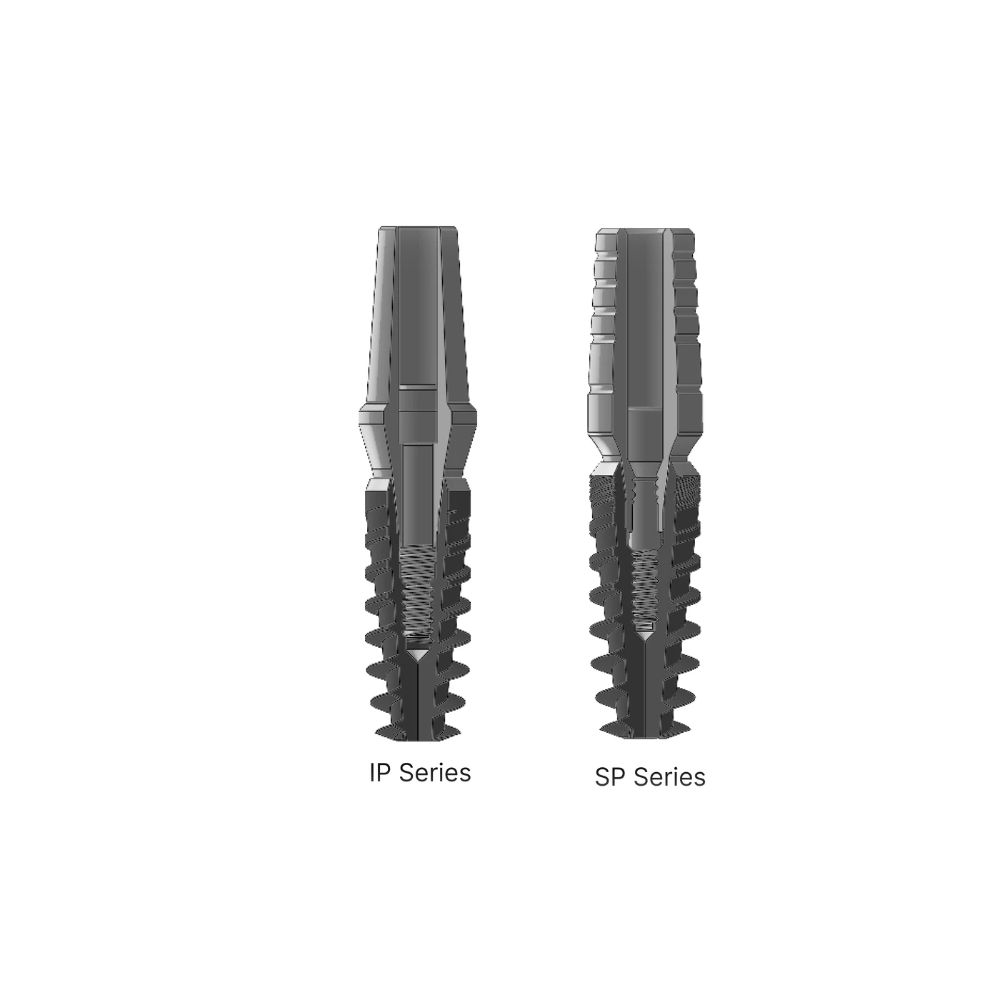
The name on the box tells you less than the platform underneath it. IP and AK run on the NP connection, SP, S-Fix Pro and AK* on RP, ZE on its own zygomatic multi-unit connection, and B and C are one-piece implants that carry their prosthetic post already, so they have no separate abutment connection at all. AK* is the one most often got wrong: it sits on RP in spite of the AK name, and takes the SP component set rather than AK’s.
- NP connection, 2.25 mm A/F hex, 12° Morse taper, M1.6 screw: IP Series, AK Series
- RP connection, 2.50 mm A/F hex, 11° Morse taper, M2.0 screw: SP Series (S-Fix Pro), AK* Series
- Zygomatic multi-unit, 2.25 mm A/F external hex: ZE Series
- One-piece, prosthetic post integral to the implant: B Series, C Series
IP+ runs on its own connection, 2.45 mm A/F with a 45° taper and an M1.8 screw. It does not take NP components, and its own set is not published yet.
-
Two sets cover the whole bone-level range
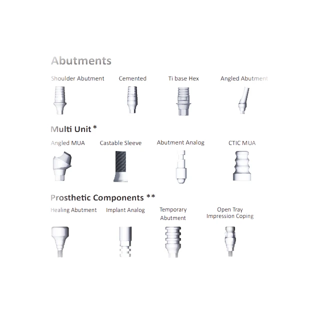
There are not nine component ranges to learn. The bone-level implants share two sets of 77 components each, one for NP and one for RP, and the two are organised identically, so a clinician who knows where to look in one knows where to look in the other. Each set is divided into the same five groups.
- Multi-unit abutments: straight and angled, with collars, healing caps, screws, copings, sleeves and analogs
- Implant-level restorative abutments: engaging and non-engaging options for single-unit and splinted restorations, including screw-retained and cement-retained workflows where applicable
- Overdenture solutions: ball and locator abutments for removable work
- Healing, impression and temporary: healing abutments, impression copings and temporary abutments
- Scan and digital workflow: scan body, digital analog and implant analog
-
Read the code, not the name
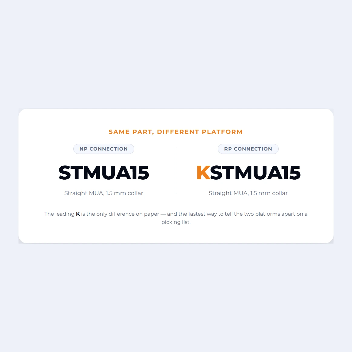
Component names repeat across platforms. A straight multi-unit abutment with a 1.5 mm collar exists on both NP and RP, and they are different parts. The codes do not repeat, and they are built to be read: the family, then the geometry, then the dimensions in the order the catalogue quotes them. On the RP set the code carries a leading K, which is the fastest way to tell the two platforms apart on a picking list.
NP codesIP Series, AK Series
- STMUA15
- Straight MUA, 1.5 mm collar
- 17MUA25
- 17° angled MUA, 2.5 mm collar
- UCH4001
- UCLA, with hex, 4.15 × 1 mm
- TBH3805
- Ti Base, hex, Ø3.80 × 0.5 mm
- HA4023
- Healing abutment, 4.15, 2 mm collar × 3 mm
RP codesSP Series (S-Fix Pro), AK*
- KSTMUA15
- The same part on RP, K-prefixed
- K17MUA25
- 17° angled MUA, 2.5 mm collar
- KTBH4506
- Ti Base, hex, Ø4.50 × 0.6 mm
- KHSB-12
- Scan body, 12 mm
- KIA01
- Implant analog
Record the implant system, platform and implant article/reference code at placement. "4.0 × 11" with no series and no code cannot be restored by anyone who was not in the room.
-
Thirteen components are shared, and they are the ones above the abutment
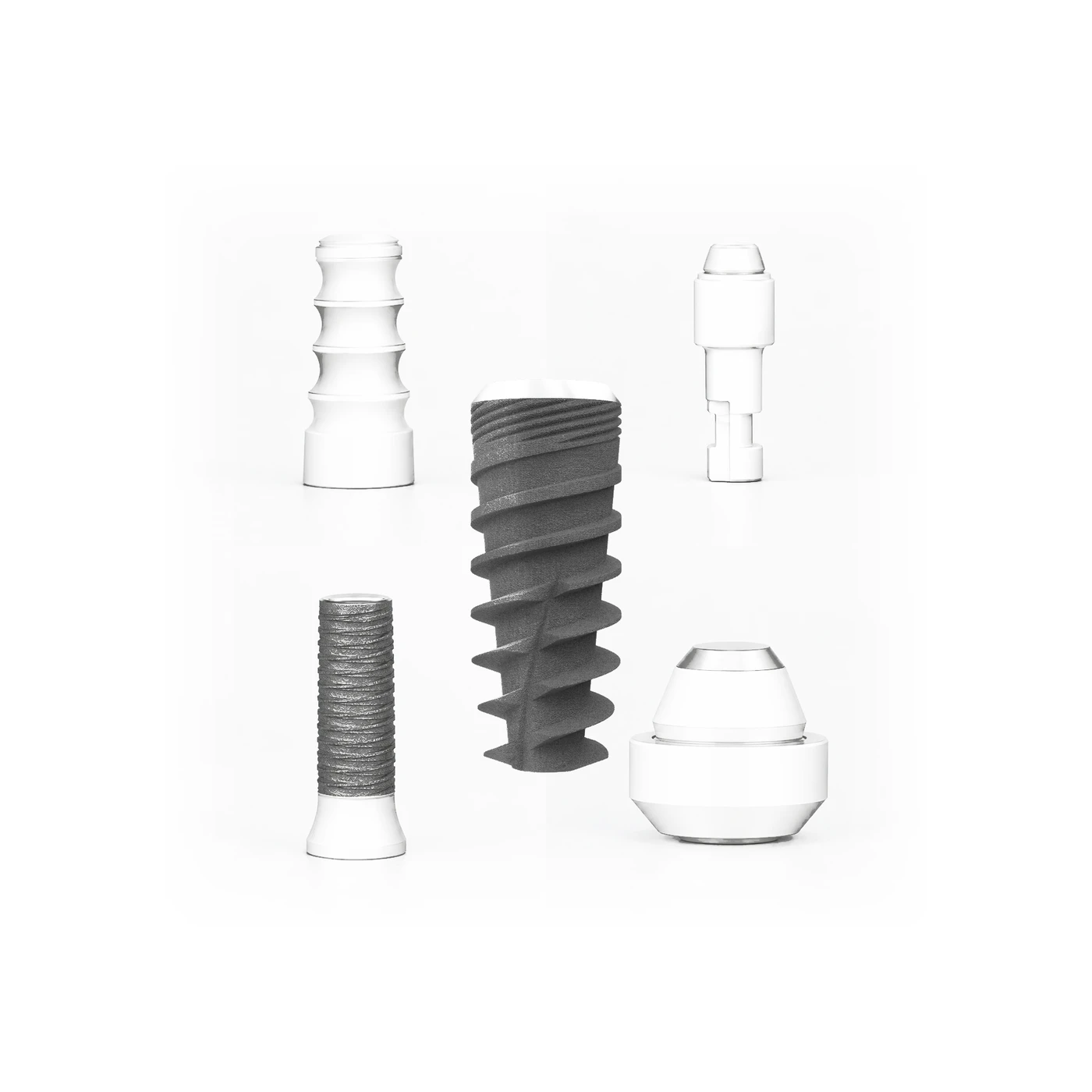
Not every part is platform-specific. Thirteen codes appear unchanged in both the NP and the RP set, and they are all components that sit on top of a multi-unit abutment rather than on the implant itself. Once a multi-unit is in place the connection above it is the same whichever platform it was screwed into, so the healing cap, the copings, the prosthetic screw and the analogs are common parts.
- HCMUA healing cap, PSMUA prosthetic screw (M1.4)
- OTICMUA and CTICMUA open and closed tray impression copings
- TCMUA temporary coping, CSPMUA castable sleeve, AAMUA abutment analog
- DSBMUA scan body, DAMUA digital analog, DTBMUA digital Ti base
The rule only holds above the multi-unit abutment. Anything that touches the implant is platform-specific, and on RP it carries the K.
-
Choose engaging or non-engaging
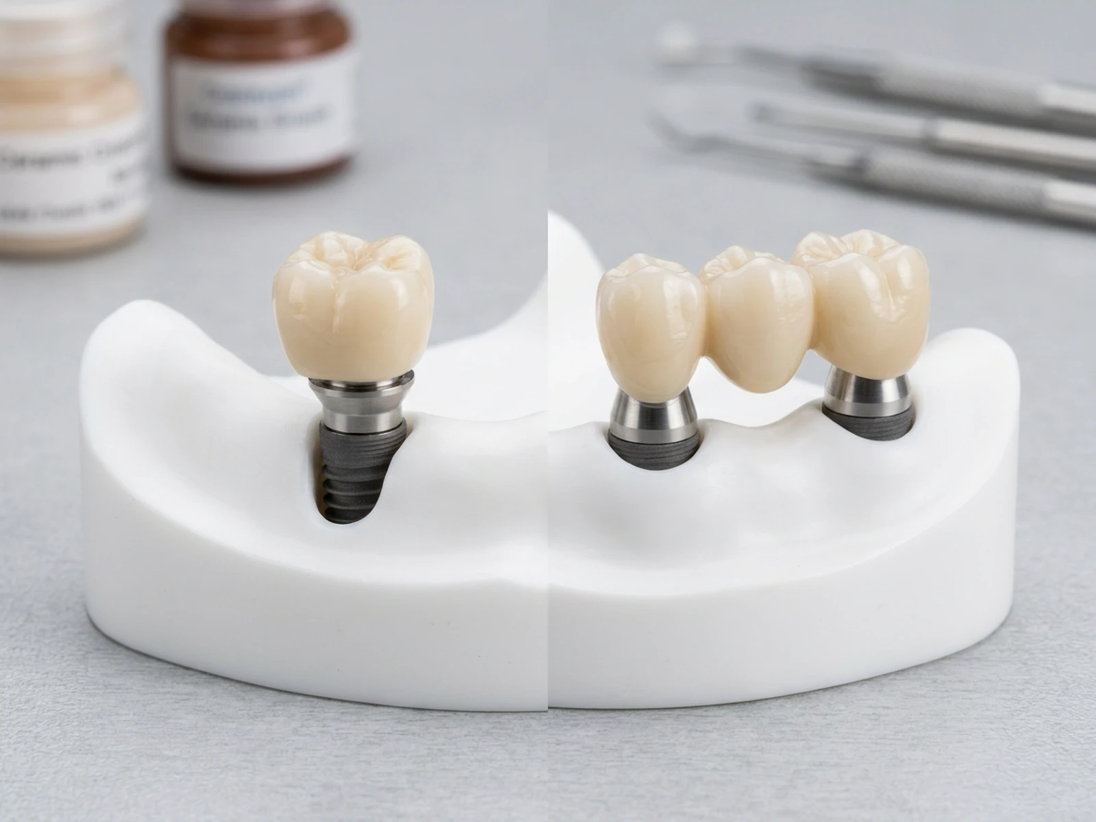
Most single-unit abutments are listed twice, once with hex and once without, and the choice is structural rather than a preference. Engaging components are generally indicated for single-unit restorations where anti-rotational stability is required. Non-engaging components are commonly used for splinted multi-unit restorations to facilitate a common path of insertion. UCLA and Ti Base abutments both come in the two forms, coded UCH and UCNH, TBH and TBNH.
- Single crown: engaging, the hexed version
- Splinted bridge across two or more implants: non-engaging
- Multi-unit abutments are already non-engaging by design, so the question does not arise on them
-
Match the collar to the tissue, not to the crown
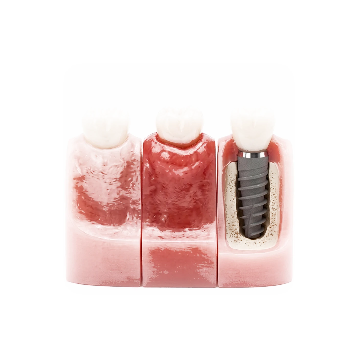
Healing abutments and single-unit abutments are listed by platform diameter, collar height and overall height, in that order. Select collar height according to the measured soft-tissue height, intended restorative margin, emergence profile and the requirements of the selected prosthetic component. The healing abutments run in 4.15 and 5.2 mm platform diameters on NP, and the RP set carries the equivalent range for its own 4.0, 4.5 and 5.5 mm connection sizes.
-
The zygomatic and one-piece sets are separate
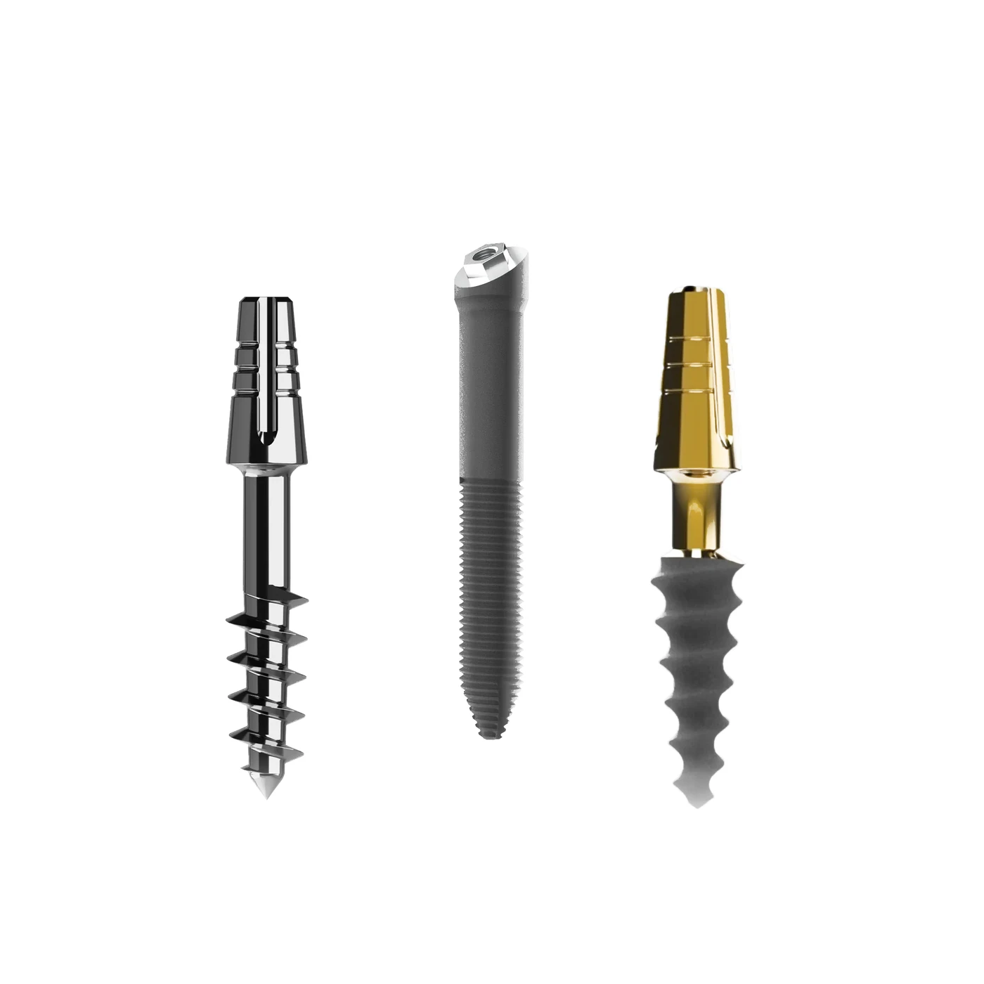
ZE has eleven dedicated components on its own 2.25 mm A/F external-hex connection, covering straight and angled multi-units at 17° and 25°, healing caps, impression and temporary copings, analogs and screws. The one-piece B and C implants need far less, because the abutment is part of the implant: an impression coping, an analog and a burn-out cap. Those three are supplied on request and do not yet carry published article codes.
The B and C components are ordered by description rather than by code until the codes are assigned. Say which series when you ask.
-
Impression or scan, then the laboratory
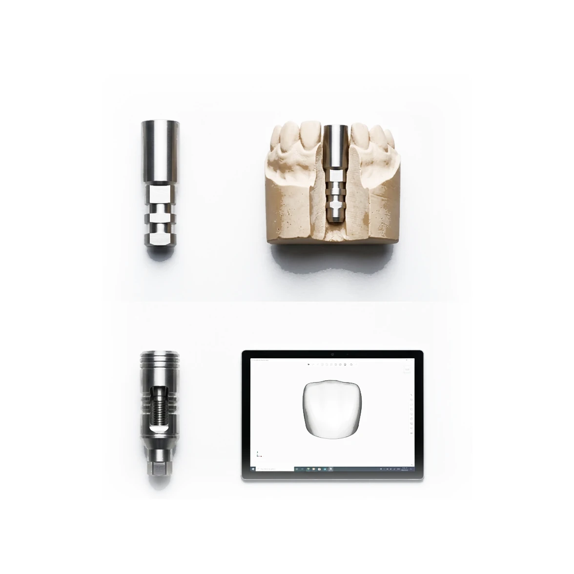
Both platforms support a conventional impression and a digital scan, and the component set carries the parts for either. The conventional route uses an open or closed tray impression coping and an implant analog, which the laboratory pours into the model. The digital route uses a scan body to record the implant position with an intraoral scanner. The corresponding digital library is selected in the CAD software for restoration design. When a physical 3D-printed model is required, the corresponding digital analog is positioned in the printed model.
- Conventional: impression coping, then the implant analog, IA01 on NP and KIA01 on RP
- Digital: scan body HSB-12 on NP or KHSB-12 on RP, then the digital analog DA02 or KDA02
- Restoring on a multi-unit abutment instead: DSBMUA and DAMUA, which are the same on both platforms
-
Overdentures run on ball or locator abutments
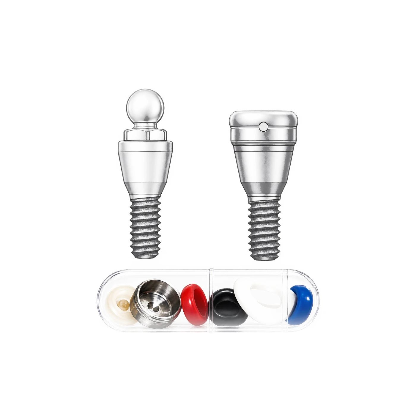
An implant-retained overdenture gains retention and stability from implant attachments while support may be provided by the implants, residual ridge, or a combination depending on the prosthetic design, and the portfolio carries two routes to it. A ball abutment presents a round stud that the denture clips over, and a locator abutment presents a lower-profile connection in the same role. Both are listed by collar height: select the appropriate collar height according to peri-implant tissue height while also considering prosthetic space, implant angulation and the requirements of the selected attachment system. Both are supplied with a housing that is processed into the denture and an analog for the laboratory model.
- Ball abutments in 1, 3 and 5 mm collars: BA01, BA03 and BA05 on NP, KBA01, KBA03 and KBA05 on RP
- Locator abutments in 0, 2, 4 and 6 mm collars: LA00 to LA06 on NP, KLA00 to KLA06 on RP
- The housing packages and the ball abutment insertion tool are common parts: ball housing BAHP1 or BAHP2, locator housing LAHP2, and the insertion tool BAIT01
The abutment touches the implant, so it is platform-specific and carries the K on RP. The housing processed into the denture sits above it and carries no K on either platform.
-
Order and record by code
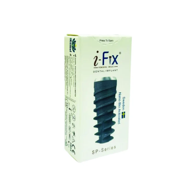
The code on the package is the identity of the part. Record the implant system, platform and implant article/reference code at placement, then add the article codes of prosthetic components to the patient record as they are selected and used during the restorative workflow, and give them to the laboratory with the case. It is the one piece of information that survives a change of clinician, a change of laboratory and a patient moving practice, which is exactly when a restoration needs to be matched years later.
-
One workflow connects every stage above
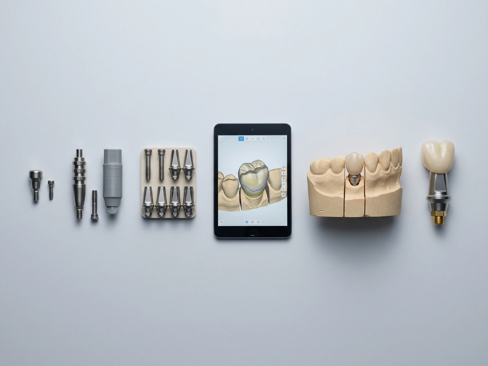
Every stage above answers one question in a single sequence, and it is worth seeing that sequence as one line rather than as ten separate topics: a healing abutment shapes the tissue, an impression or a scan records the site, the abutment is selected against tissue height, restorative margin and restoration type, the laboratory or CAD-CAM builds to that selection, a try-in verifies fit before delivery, and the restoration is delivered. The connection, the code and the component set exist to get each step right; this is the order they run in.
- Healing abutment shapes the emergence profile during soft-tissue healing
- Impression or scan records the implant position for the laboratory
- Abutment selection follows tissue height, restorative margin, engaging/non-engaging need and restoration type
- Laboratory or CAD-CAM builds the restoration on the selected abutment or Ti base
- Try-in allows verification of fit, proximal contacts, occlusion, emergence profile and aesthetics as applicable before final delivery
- Final restoration is delivered according to the applicable restorative protocol, and the components/article codes used are documented in the patient record
02 More guides
The rest of the series.
The placement sequence stage by stage, from treatment planning through to the prosthetic phase.
Open Extraction and site preparationHow a site is assessed, prepared and timed before an implant goes into it.
Open Hygiene and maintenanceWhat the implant and its components are made of, and what that means for cleaning and recall.
Open