
i-Fix Education
Placing an i-Fix implant.
The placement sequence stage by stage, from treatment planning through to the prosthetic phase.
For qualified clinicians. This guide explains how the i-Fix system is organised. It does not replace the Instructions for Use supplied with each product, which carries the complete instructions, precautions and clinical use information.
Drawn from the current IP Series and SP Series brochures. This is orientation, not a substitute for the Instructions for Use — every diameter, drill sequence and precaution that governs a real case is published there and on the protocol chart supplied with the kit.
- Treatment planning
- Select the implant system
- Select diameter and length
- Assess bone condition
- Follow the i-Fix drilling protocol
- Implant placement
- Assess primary stability
- Healing
- Prosthetic restoration
How it works
Each stage names what happens and the one thing that most often goes wrong there. Numbers stay in the IFU, where they can be revised without a stale copy living on a web page.
-
Plan to the restoration, not to the socket
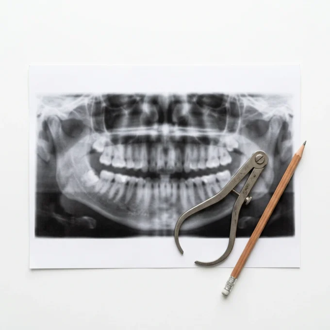
Assessment comes before selection. Evaluate the patient clinically and radiographically, then plan the implant position against the restoration that is actually intended and the anatomy that is actually available. A fixture placed where the bone is most generous is not always a fixture the laboratory can restore, which is why the prosthetic requirement leads and the position follows.
- Available bone height and width
- Bone quality, and the condition of the soft tissue over the site
- Adjacent roots and the anatomical structures near the site
- Implant diameter and length
- Position, angulation and depth, set by the proposed restoration
Choosing a position the bone will accept but the planned restoration cannot use.
-
Select the system, and with it the platform
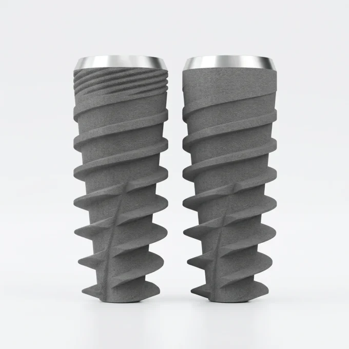
Select the implant system and prosthetic platform before surgery. i-Fix Pro (IP Series) uses the NP prosthetic connection, and S-Fix Pro (SP Series) uses the RP prosthetic connection. Their prosthetic components are platform-specific, so restorative components are selected according to the connection used at implant placement, and that is what the laboratory will be ordering against months later. Both bodies are built on the same design intent: an expanding tapered body with a two-start thread and a varying thread profile, a back-tapered coronal region, twin cutting flutes and twin apical cutting blades, a combination intended to hold the fixture firmly as it seats and to condense bone gradually rather than abruptly.
i-Fix Pro (IP Series)NP conical connection
- Internal hex
- 2.25 mm A/F
- Morse taper
- 12°
- Prosthetic screw
- M1.6
- Surface
- Nano Bio-Activated
- Diameters
- 3.5 / 4.0 / 4.5 / 5.0 / 5.5 mm
S-Fix Pro (SP Series)RP conical connection
- Internal hex
- 2.50 mm A/F
- Morse taper
- 11°
- Prosthetic screw
- M2.0
- Surface
- Nano Bio-Activated
- Diameters
- 3.6 / 4.0 / 4.5 / 5.0 / 6.0 mm
Reading AK* as an NP system because of the AK name. It seats on RP and takes the SP component set.
-
Prepare the site to the plan
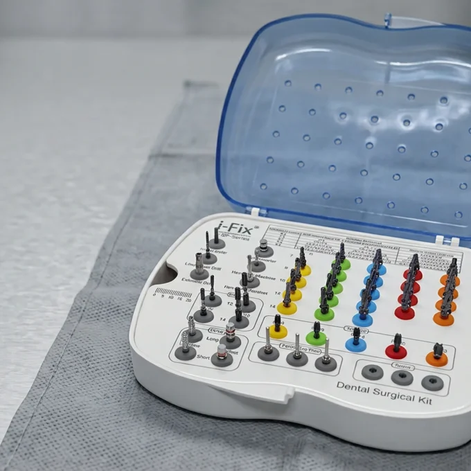
Each i-Fix surgical kit holds a lance drill, a pilot drill, step drills, paralleling pins, cortical drills and the implant drivers for the system it serves, and the drills sit in the tray in the same order the drilling chart prints them. Check that the tray in front of you and the chart for the selected system agree before the first drill enters bone.
- Mark the planned implant position
- Open the initial osteotomy with the pilot drill for the selected system
- Check angulation and direction with a paralleling pin where required
- Continue the sequential preparation for the chosen diameter and the bone condition
A tray restocked with a drill from another series. If the tray and the chart disagree, stop.
-
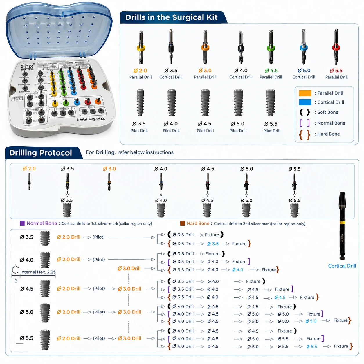
Follow the chart for the system in hand
i-Fix Pro (IP Series) and S-Fix Pro (SP Series) each have their own surgical kit and their own drilling protocol, and the sequence on each protocol changes with both the implant diameter and the density of the bone. The brochures separate soft, normal and hard bone, because an osteotomy prepared correctly for dense bone leaves a soft site with little to hold on to. Read the implant diameter and the bone condition against the current approved protocol and IFU for the system being placed. No single drilling sequence applies to both systems, and this page deliberately does not print one.
- Use the drill sequence published for the selected system
- Hold the planned depth and angulation
- Irrigate adequately throughout preparation
- Use the cortical drill where the protocol indicates it
i-Fix Pro (IP Series)NP connection
- Surgical kit
- IP surgical kit
- Drilling protocol
- IP drilling protocol
S-Fix Pro (SP Series)RP connection
- Surgical kit
- SP surgical kit
- Drilling protocol
- SP drilling protocol
Skipping a step. The next drill then cuts more than it was designed to, which raises both heat and insertion torque.
-
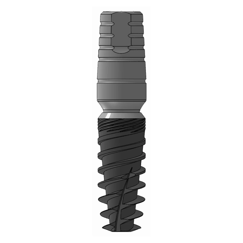
Insert along the planned axis
Once the osteotomy is complete, engage the fixture with the implant driver for that system and seat it along the axis and to the depth that were planned. Implants are supplied sterile and co-packed with a cover screw, and the zygomatic system is co-packed with its mount as well. Insertion torque and speed are given in the Instructions for Use for the series in hand and are not repeated here, because they differ by series and by bone density.
- Monitor insertion resistance as the fixture seats
- Hold the planned position and angulation
- Confirm the final implant depth
- Assess primary stability once the implant is placed
Handling the implant surface. The Nano Bio-Activated finish is the part that meets bone first.
-
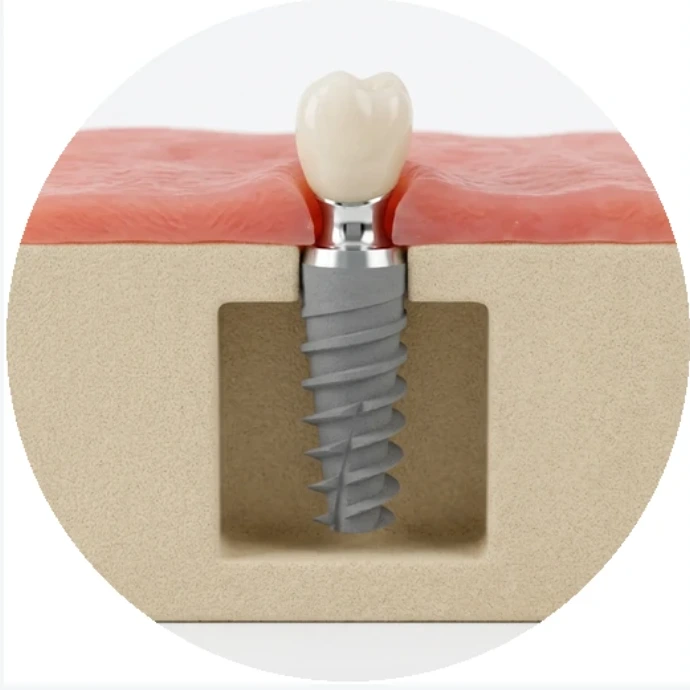
Read primary stability as one input
Primary stability is how firmly the implant is held at the moment it is placed. It is read clinically from the insertion torque and, where the equipment is available, from resonance frequency analysis, reported as an ISQ value. Both are single readings taken from a much wider clinical picture, and the decision that follows, whether to submerge the implant, fit a healing abutment or load it, belongs to the complete situation in front of the surgeon rather than to either number on its own.
Treating one torque figure or one ISQ reading as the decision.
-
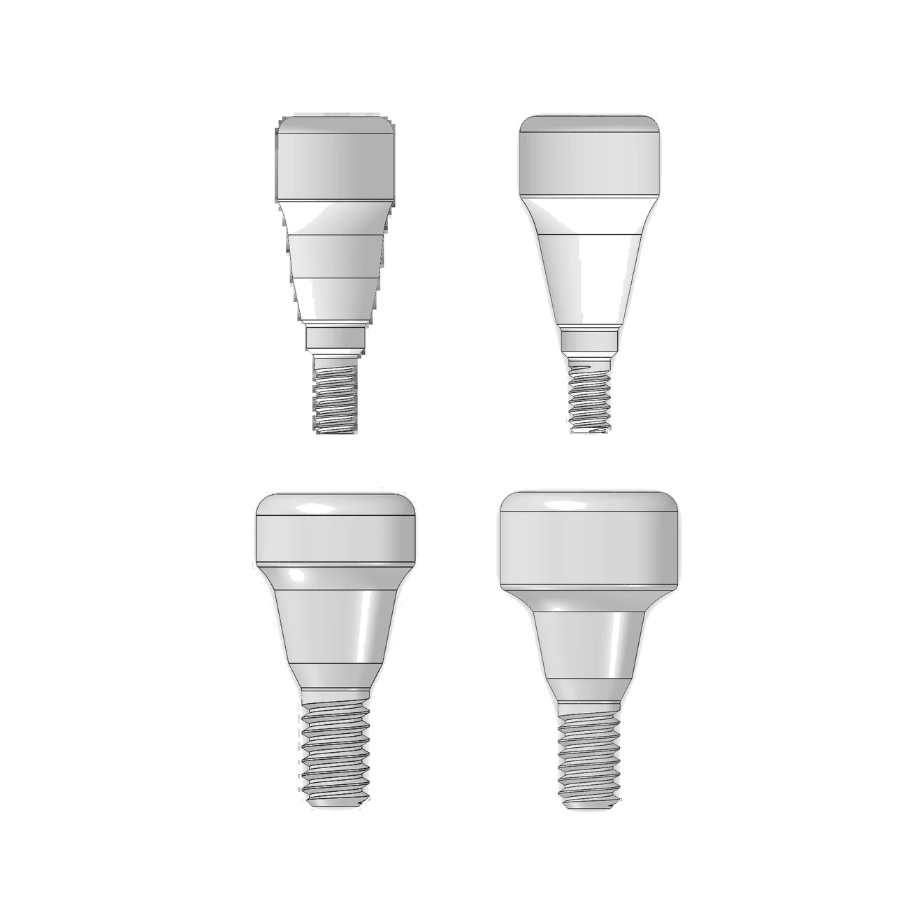
Heal submerged or transmucosally
An implant can be left to heal submerged beneath a cover screw, with the soft tissue closed over it, or transmucosally with a healing abutment passing through the tissue. Which of the two suits a case is a clinical decision taken from the situation at placement. IP Series and SP Series are both supplied with a cover screw, and both have healing abutment options within their component sets.
Ordering a healing abutment against the series name rather than against the connection it seats on.
-
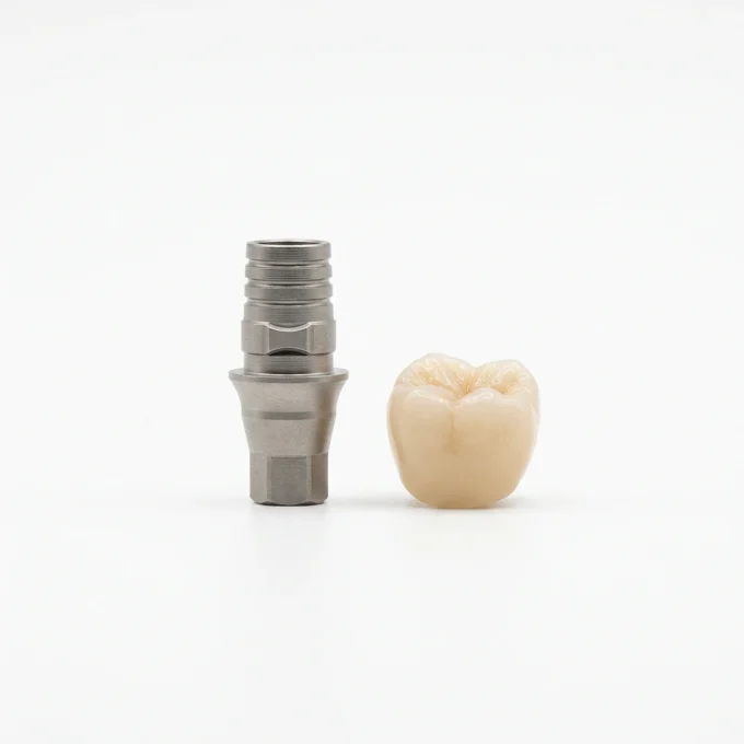
Restore on the platform you placed
After healing and clinical assessment, the restoration follows the workflow planned at the outset. Both systems support a conventional impression route and a digital one. The digital route runs from a scan body on the implant, through an intraoral scan, into a digital implant analog or CAD workflow, on to a Ti-base or the prosthetic component selected for the case, and finally to the restoration itself. Which components are available to you was settled back at stage two, when the platform was chosen.
Ordering components by display name. The same component name exists on more than one platform, and those are different parts.
02 Drilling
The published sequence.
The same matrix printed on the protocol chart supplied with each surgical kit. Fewer drills in soft bone, the full sequence in dense bone.
| Implant diameter | Soft bone (D3–D4) | Medium bone | Dense bone (D1–D2) |
|---|---|---|---|
| 3.5 mm | 2.0 | 2.0 → 2.4 → 2.8 | 2.0 → 2.4 → 2.8 → 3.2 |
| 4.0 mm | 2.0 → 2.4 | 2.0 → 2.4 → 2.8 → 3.2 | 2.0 → 2.4 → 2.8 → 3.2 → 3.6 |
| 4.5 mm | 2.0 → 2.4 → 2.8 → 3.2 | 2.0 → 2.4 → 2.8 → 3.2 → 3.6 | 2.0 → 2.4 → 2.8 → 3.2 → 3.6 → 4.2 |
| 5.0 mm | 2.0 → 2.4 → 2.8 → 3.2 → 3.6 | 2.0 → 2.4 → 2.8 → 3.2 → 3.6 → 4.2 | 2.0 → 2.4 → 2.8 → 3.2 → 3.6 → 4.2 → 4.6 |
Refer to the applicable i-Fix IFU for complete instructions, precautions and clinical use information. Final treatment planning remains the responsibility of the qualified clinician.
Full surgical protocols03 More guides
The rest of the series.
Which component set belongs to which connection, how to read an article code, and the order a restoration is assembled in.
Open Extraction and site preparationHow a site is assessed, prepared and timed before an implant goes into it.
Open Hygiene and maintenanceWhat the implant and its components are made of, and what that means for cleaning and recall.
Open