
On this page 7 sections
- The rule that governs every component below
- Multi-unit abutments: the full-arch component set
- Single-unit abutments: screw-retained and cement-retained
- Overdentures, healing, impression and temporary parts
- The digital route: scan bodies, analogs and libraries
- The dental implant surgical kit, and the sequence inside it
- Ordering without getting it wrong
Choosing a dental implant prosthetics manufacturer is a separate decision from choosing an implant, and most clinics make it by accident. An implant is roughly a fifth of what a restorative case orders. The rest is abutments, screws, copings, caps, analogs and scan bodies, and getting one of them wrong is the most common reason a case stalls between the surgery and the laboratory. This page lists the whole component set for the NP and RP connections with the article codes as printed in the catalogue, and covers the surgical kit that comes before any of it.
The rule that governs every component below
Prosthetic components are cut for the connection platform, not for the implant series. An abutment machined for the NP connection seats on any NP implant in the range and will not seat on an RP implant, regardless of which series either belongs to. That is why the prosthetics catalogue on this site is organised by platform rather than by product line: it is organised the way the parts behave.
| NP connection | RP connection | |
|---|---|---|
| Hex across flats | 2.25 mm | 2.50 mm |
| Taper | 12° Morse taper | 11° Morse taper |
| Abutment screw | M1.6 | M2.0 |
| Implant series on it | IP Series, AK Series | SP Series, S-Fix Pro, AK* Series |
| Implant diameters | Ø 3.5 – 5.5 mm | Ø 3.6 – 6.0 mm |
A dental implant kit for clinics is built around that same platform boundary, which is why there is one tray per connection rather than one per series. Types of dental implant connections are covered in full on the connections reference, and the short version is that the two published i-Fix platforms differ in three numbers and share almost nothing else.
Multi-unit abutments: the full-arch component set
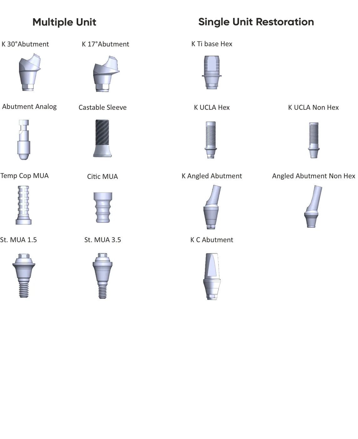
A multi-unit abutment converts an implant into a common prosthetic platform at a chosen height and angle, so that several implants placed at different angulations can carry one screw-retained bridge. It is the component that makes full-arch work practical, and it comes with its own family of parts that only fit it.
| Component | Code |
|---|---|
| Straight MUA, 1.5 mm collar | STMUA15 |
| Straight MUA, 3.5 mm collar | STMUA35 |
| 17° angled MUA, 2.5 mm collar | 17MUA25 |
| 17° angled MUA, 3.5 mm collar | 17MUA35 |
| 30° angled MUA, 3.5 mm collar | 30MUA35 |
| 30° angled MUA, 4.5 mm collar | 30MUA45 |
| Healing cap MUA | HCMUA |
| Abutment screw (M1.6) MUA | ASMUA |
| Prosthetic screw (M1.4) MUA | PSMUA |
| Temporary coping MUA | TCMUA |
| Open tray impression coping MUA | OTICMUA |
| Closed tray impression coping MUA | CTICMUA |
| Abutment analog MUA | AAMUA |
| Castable sleeve MUA (plastic) | CSPMUA |
| Protection analog MUA | PAMUA |
| Digital analog MUA | DAMUA |
| Digital scan body MUA | DSBMUA |
| Digital Ti base MUA | DTBMUA |
The angle and collar height are chosen together. The angle corrects for implant angulation so that the screw access channels emerge somewhere the restoration can accept them, and the collar height lifts the prosthetic platform clear of the soft tissue so the restoration is not fighting the gum. A 17° abutment on a 3.5 mm collar and a 30° abutment on a 4.5 mm collar are different answers to the same problem of an implant that came in at an angle in tissue that is thick.
Note the two screws. The abutment screw at M1.6 holds the multi-unit abutment onto the NP implant. The prosthetic screw at M1.4 holds the restoration onto the abutment. They are not interchangeable, and on the RP platform the abutment screw is M2.0 instead.
Single-unit abutments: screw-retained and cement-retained
For single crowns and short bridges, the choice is between a screw-retained restoration, which can be removed and refitted, and a cement-retained one, which hides the screw access but is difficult to retrieve. The component list reflects both routes.
| Component | Codes |
|---|---|
| UCLA abutment, with hex | UCH4001 (4.15 × 1), UCH5001 (5.2 × 1.5) |
| UCLA abutment, non-hex | UCNH4001, UCNH5001 |
| Ti base abutment, hex, Ø3.80 | TBH3805 (× 0.5), TBH3815 (× 1.5), TBH3830 (× 3.0) |
| Ti base abutment, non-hex, Ø3.80 | TBNH3805, TBNH3815, TBNH3830 |
| Shoulder abutment, 4.15 collar | SAH4001 / 4002 / 4003 (non-hex: SANH…) |
| Shoulder abutment, 5.2 collar | SAH5001 / 5002 / 5003 (non-hex: SANH…) |
| Angled abutment 15° | 15A4001, 15A4002, 15A5001, 15A5002 |
| Angled abutment 25° | 25AH4001, 25AH4002 |
| Cemented abutment | CA4001 (Ø4.15), CA5001 (Ø5.20) |
The hex and non-hex distinction is the one most often ordered wrong. A hexed abutment engages the implant's anti-rotation feature and is what a single crown needs, because a single unit has nothing else stopping it turning. A non-hex abutment does not engage it, which is exactly what a multi-unit bridge wants: with several implants splinted together, rotation is already prevented, and non-engaging abutments let the bridge seat despite small angular differences between the implants.
A Ti base is the component that carries the digital workflow. It is a titanium interface that bonds to a milled zirconia or lithium disilicate structure, so the restoration gets a titanium-to-titanium connection at the implant and a ceramic surface at the tooth. The three heights, 0.5, 1.5 and 3.0 mm, exist because the amount of titanium visible below the ceramic depends on how deep the implant sits and how thick the tissue is.
Overdentures, healing, impression and temporary parts
Three further groups complete the set. Overdenture solutions cover ball and locator abutment components for removable prostheses, published for both the NP and RP connections. Healing abutments, impression copings and temporary abutments are listed in 4.15 and 5.2 mm collar diameters on NP, and in 4.0, 4.5 and 5.5 mm on RP. The scan and digital workflow group carries the scan bodies and analogs that the laboratory needs.
Impression copings come in open-tray and closed-tray versions and they are not alternatives to one another so much as answers to different clinical situations. An open-tray coping stays in the impression when the tray is removed, which is more accurate across multiple implants and requires a tray with a hole in it. A closed-tray coping stays in the mouth and is transferred to the impression afterwards, which is easier in a posterior site where opening the mouth wide enough for an open tray is not realistic.
The digital route: scan bodies, analogs and libraries
Digital implant abutment design starts one step earlier than most people expect. A digital case replaces the impression coping with a scan body, which is a machined part with a known geometry that the intraoral or lab scanner reads. The design software recognises the scan body's shape, and from it derives exactly where the implant sits and at what angle. That is why the scan body has to be the right one for the connection: the software is not measuring the implant, it is recognising the part.
From there the case needs the implant library, which is the file that tells the CAD software the real connection geometry so the designed Ti base interface actually fits. Those are published per connection platform.
The dental implant surgical kit, and the sequence inside it
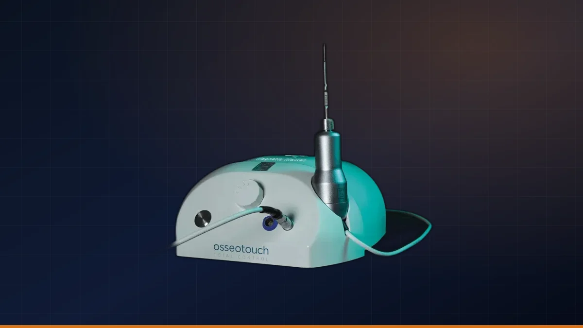
Working backwards from the restoration lands you at the kit. An implant surgery tool kit for dentists is not an accessory to the implant, it is half of what makes the specification reachable. There is one tray per connection platform, each built around the diameter and length envelope of the series it serves, and each reproduced from the current product catalogue rather than assembled ad hoc. The drilling sequence inside it is published, and it changes with bone quality rather than with the implant alone.
| Implant Ø | Soft bone | Medium bone | Dense bone |
|---|---|---|---|
| 3.5 mm | 2.0 | 2.0 → 2.4 → 2.8 | 2.0 → 2.4 → 2.8 → 3.2 |
| 4.0 mm | 2.0 → 2.4 | 2.0 → 2.4 → 2.8 → 3.2 | 2.0 → 2.4 → 2.8 → 3.2 → 3.6 |
| 4.5 mm | 2.0 → 2.4 → 2.8 → 3.2 | 2.0 → 2.4 → 2.8 → 3.2 → 3.6 | 2.0 → 2.4 → 2.8 → 3.2 → 3.6 → 4.2 |
| 5.0 mm | 2.0 → 2.4 → 2.8 → 3.2 → 3.6 | 2.0 → 2.4 → 2.8 → 3.2 → 3.6 → 4.2 | 2.0 → 2.4 → 2.8 → 3.2 → 3.6 → 4.2 → 4.6 |
Refer to the applicable i-Fix instructions for use for complete instructions, precautions and clinical use information. Final treatment planning remains the responsibility of the qualified clinician.
Ordering without getting it wrong
- 01 Confirm the platform, not the series
Check which connection the implant in the mouth is on. AK* is RP despite the AK name, and IP+ is neither NP nor RP.
- 02 Decide screw-retained or cement-retained
That decides whether the case runs on multi-unit abutments and prosthetic screws, or on shoulder and cemented abutments.
- 03 Decide hex or non-hex
Hexed for a single unit, non-engaging for a splinted multi-unit restoration.
- 04 Add the collar height to the order
The collar has to clear the soft tissue. It is a measured decision, not a default.
- 05 Add the laboratory parts
Impression coping or scan body, plus the analog. A case that arrives at the lab without an analog stops there.